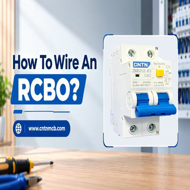
RCBO is an electrical safety switch which integrates over current protection and residual current protection into one unit.
It is important to correctly wire the RCBO because improper wiring of the line, neutral, or earthing may result in inadequate protection or unnecessary tripping of the device.
Different RCBO models may have varying design layouts, especially regarding the terminals and neutral arrangement.
Hence, the user should always refer to the markings of the device itself and its wiring diagram provided by the manufacturer.
Today, we will explore all you need to know how to wire an RCBO. We will cover from its terminals to the tools used in the process, safety measures involved, step-by-step process, testing procedures, and many other aspects of this process such as common errors, troubleshooting tips, and considerations for selection.
Qu'est-ce qu'un RCBO ?
RCBO is short form of Residual Current Circuit Breaker with Overcurrent.
RCBOs integrate two forms of protection in one: residual current protection and overcurrent protection.
Residual current protection detects an unbalance of the current flowing through the conductors in the protected circuit.
The unbalance is caused by leaking current to earth through faulty insulation, faulty equipment, and other paths.
If the residual current level detected exceeds the predetermined level in the device, the RCBO may interrupt the circuit.
Overcurrent protection protects from overload and short circuits, in accordance with the rated values and characteristic curves of the device.
RCBOs are typically used in final circuit protection. But the circuits can have their own form of residual current protection and overcurrent protection, RCBOs can be used for selective circuit protection on the distribution board.
Proper selection is critical as the voltage, current rating, residual current sensitivity, type, pole number, and breaking capacity should match the application.
RCBO Wiring Diagram Explained
A typical wiring arrangement for an RCBO consists of an incoming phase and neutral, an RCBO, a protected outgoing phase and neutral, and a protective-earth conductor.
1. Incoming Supply
The incoming line and neutral originate from the distribution system and connect to the appropriate RCBO supply terminals. The exact terminal positions depend on the product design.
2. RCBO Protection Path
Line and the neutral, if there is one, pass through the protective and sensing arrangement of the device.
RCBO controls the circuit, and under certain conditions, it may interrupt the circuit operation.
3. Outgoing Load Connections
The protected line and neutral supply the final circuit. Both must remain correctly associated with the same RCBO.
4. Protective Earth Path
The earth conductor would typically be connected to the earth arrangements provided in the distribution board, not as an alternative to the neutral connection.
5. How Current Imbalance Is Detected
In normal conditions, the current that leaves through the protected line and comes back through the corresponding neutral forms the right relation. In case some of the current goes to earth through an unwanted way, it may result in imbalance.
The RCBO’s residual current detection system notices this difference. If the residual current exceeds the threshold value of the device, the trip mechanism breaks the circuit.
RCBO Vs RCD Vs MCB
An RCBO performs two functions which might be performed by different protective devices.
An RCD provides residual current protection but is not usually an overcurrent protection device.
An MCB offers overcurrent protection but is not a residual current protection device.
| Device | Protection contre les fuites à la terre | Protection contre les surcharges | Protection contre les courts-circuits | Protection individuelle des circuits | Application type | |
|---|---|---|---|---|---|---|
RCBO |
Oui |
Oui |
Oui |
Oui |
Individual | |
RCD/RCCB |
Oui |
Non |
Non |
Can protect groups |
Residual-current protection | |
MCB |
Non |
Short-duration fault withstand |
Oui |
Oui |
Oui |
Circuit overcurrent protection |
Therefore, an RCBO can combine functions in one device and can help provide dedicated protection for individual circuits.
The exact arrangement depends on the electrical installation and applicable requirements.
RCBO Terminals And Wiring Components
Understanding the terminals is important before starting RCBO wiring.
Line Terminals
The line terminals are responsible for supplying and carrying the current of the load that has to be protected.
In one case, one terminal will be connected to the incoming source, while the other will be connected to the outgoing line.
Neutral Terminals
If the RCBO acts as a switch and monitor on the neutral conductor, then the incoming neutral conductor and the protected neutral conductor should be properly wired in accordance with the manufacturer’s diagram.
Otherwise, there may occur a malfunctioning of the RCBO or improper operation of the device.
Earth Connection
The protective earthing conductor offers a path for the fault current. This conductor allows protective devices to work. The conductor has to be connected to the correct earth bar or terminal installation.
It is important to distinguish between neutral and protective earthing. They are different conductors.
RCBO Wiring Accessories
Standard installation components are a distribution board, DIN rail, conductors of the right size, suitable terminals, insulated tools, circuit labeling, and correct test equipment.
Selection of conductor sizes and terminal layout must take into consideration the design of the installation and manufacturer’s recommendations.
Safety Precautions Before RCBO Wiring
Electrical safety is paramount to the process of installation. Installation within a distribution panel exposes an individual to dangerous voltages and fault currents.
1. Isolate the Electrical Supply
Disconnect the relevant upstream isolator and proceed to conduct a safe isolation process. When necessary, prevent accidental re-energization while working.
2. Verify the Circuit Is De-Energized
Do not depend on the switch being OFF alone. Make sure there is no voltage by using a properly-rated voltage tester. The testing device must be tested based on the proper testing procedure.
3. Inspect the Existing Wiring
Inspect the insulation, terminals, cables, and any signs of overheating or damage.
Wiring that is damaged should be fixed before the protective device can be installed.
4. Confirm Circuit Compatibility
Conductors’ sizes, loads, voltage, protection devices, and circuit layout must be verified.
Selection of the RCBO should depend on the project needs and not merely on its availability.
5. Follow Manufacturer Instructions
There can be different arrangements of the terminals for RCBO units.
Follow the manufacturer’s recommendations and electrical rules.
What To Check Before Wiring An RCBO
Before installing an RCBO, confirm that the device is suitable for the circuit.
1. Check the RCBO Rating
Check for rated current, rated voltage, frequency, and breaking capacity. Current rating should match the design and capacity of conductors.
2. Check the Residual Current Rating
The value for residual current sensitivity must depend on the application and installation.
There are general values for different uses, but the proper one should never be taken for granted.
3. Check the RCBO Type
Examples of residual currents include Type AC and Type A; however, there are other residual currents depending on application.
The currents from electronic equipment may require the right residual current type.
4. Check the Number of Poles
There are RCBOs that may vary according to the pole configurations, such as one-pole and neutral or two-pole.
5. Check the Trip Curve
The B and C curves are often found in low-voltage applications. It all depends on the load being used and the anticipated surge current.
6. Check the Manufacturer's Wiring Diagram
It is necessary to ensure that you check the terminals, polarity, and other connecting conditions from the manufacturer’s labeling.
It should be noted that all RCBOs have the same terminal configuration.
Tools And Materials Required
The installation should use correctly rated tools and materials. Typical requirements include:
- Correctly rated RCBO
- Distribution board and DIN rail
- Suitable electrical conductors
- Insulated screwdrivers
- Wire stripper
- Approved voltage tester
- Multimeter or suitable test equipment
- Torque screwdriver where specified
- Ferrules or terminal accessories where applicable
- Circuit labels
- Appropriate PPE
The exact tools depend on the installation and testing requirements. Test instruments must be suitable for the electrical environment and used according to their instructions.
How To Wire An RCBO: Step by Step
Below is a general installation procedure. The wiring will have to conform to the manufacturer’s diagram for the RCBO.
Step 1: Identify the Circuit to Be Protected
Determine which circuit the RCBO will protect. Confirm its supply voltage, expected load, conductor size, and circuit arrangement.
Check whether the circuit is intended for lighting, sockets, appliances, heating, or another application.
Step 2: Isolate the Power Supply
Turn off the appropriate upstream source and use safe-isolation methods.
Check that the sections of the installation are de-energized before coming into contact with the conductors.
Step 3: Mount the RCBO on the DIN Rail
Position the RCBO correctly on the distribution board’s DIN rail.
Ensure that it locks securely into place and that the installation arrangement provides appropriate clearance and access.
Step 4: Identify the Supply and Load Terminals
Identify the terminals marked as line and neutral on the device. Find out which terminals should carry the input supply voltage and which should carry the voltage across the protected load.
Do not consider the same arrangement to be similar to other RCBOs.
Step 5: Connect the Incoming Line
Route the incoming line conductor to the designated supply terminal. Insert the conductor fully and tighten the terminal according to the manufacturer’s specified torque.
Avoid leaving excessive bare conductors exposed outside the terminal.
Step 6: Connect the Incoming Neutral
Connect the neutral conductor to the correct supply side neutral terminal according to the RCBO specifications.
Ensure that the neutral conductor is connected in accordance with the manufacturer’s diagram.
Step 7: Connect the Outgoing Line
Connect the load-side line conductor to the designated outgoing terminal.
Route it toward the protected final circuit while maintaining suitable conductor organization inside the distribution board.
Step 8: Connect the Outgoing Neutral
Connect the neutral of the circuit that is protected by the RCBO to its correct load side neutral connection.
Do not connect this neutral with the neutral of another separately protected circuit.
Step 9: Connect the Protective Earth
Connect the protective conductor to the appropriate earth bar or terminal. Maintain protective-earth continuity throughout the circuit.
The protective earth must not be substituted with the neutral conductor.
Step 10: Check All Connections
Check the entire setup before recharging. Check the terminal positioning, the insulation of the conductors, polarity, terminals, no loose strands, and proper circuit isolation.
The completed wiring shall be checked with the wiring diagram provided by the manufacturer. The testing and commissioning will now follow.
How To Test An RCBO After Wiring
It will ensure that everything has been correctly installed and that the safety mechanisms are functioning properly.
- Visual Inspection: Check terminal connections, conductor routing, insulation, device mounting, circuit labeling, and overall installation condition.
- Polarity Testing:Confirm that line and neutral are arranged correctly, with the proper polarity in relation to circuit layout and device specifications.
- Continuity Testing:Appropriate continuity checks can verify protective-conductor continuity and other required circuit paths. The circuit must be safely isolated for tests requiring de-energization.
- Insulation Testing: Insulation resistance testing is helpful in detecting insulation problems or leakage paths. The testing technique used should take into consideration connected equipment that might react to test voltage levels.
- RCBO Test Button:Pressing the manufacturer’s test button should activate the residual-current trip mechanism. If the RCBO does not trip as expected, it should not be assumed to provide the required protection.
- Functional Verification: Following proper electrical testing, confirm correct operation of circuits and ensure there is no unexpected tripping. Additional testing may be required during professional commissioning.
Common RCBO Wiring Mistakes
Mixing Neutrals
A neutral from an RCBO-protected circuit must never be used with another circuit’s protected neutral. Inconsistent placement of neutrals may lead to improper tripping or failure of circuit isolation.
Reversing or Misidentifying Terminals
Connecting conductors to the wrong terminals can prevent the device from operating as intended. Supply and load markings must always be checked.
Incorrect Earth Connection
Earth and neutral play different roles. There is a danger associated with improper positioning of earth.
Using the Wrong RCBO Rating
An incorrectly selected RCBO may be unsuitable for the circuit.
Both undersized and oversized protection can create problems, so rating selection must consider the complete circuit design.
Loose Terminal Connections
Loose connections lead to increased resistance, heating, arcing, and possible connection failures. Connections must be tightened following manufacturer’s instructions.
Incorrect Conductor Size
The conductor must be suitable for the circuit’s expected load and protective-device arrangement.
Cable selection should be based on the electrical design and applicable requirements.
Ignoring Manufacturer Instructions
Neutral configuration, termination, and installation will differ among RCBOs. It is a wrong assumption to believe that all types have the same wiring system.
Why Does An RCBO Trip After Wiring?
An RCBO can trip after installation for several reasons.
- Earth Leakage:Faulty appliances, damaged insulation, moisture, or leakage from connected equipment can produce residual current.
- Neutral-to-Earth Fault:An imbalance may be caused by an earth connection in the neutral line downstream. The faulty wiring of circuits may cause similar effects.
- Overload: Excessive connected load can cause the overcurrent protection to operate. The circuit load and RCBO rating should therefore be reviewed.
- Short Circuit: Fault current is high in cases of line to neutral faults or line to earth faults.
- Incorrect Wiring: Wiring mistakes such as mixed neutrals, wrong terminals, or even backwards wiring can result in a trip.
It is important to know what caused the trip before resetting it multiple times.
How To Troubleshoot An RCBO That Keeps Tripping?
- First, consider whether the problem is caused by overcurrent or residual current.
- In cases where the procedure is safe and applicable, downstream loads may be isolated and inspected individually.
- Ensure that there are no faults on the circuit, such as damage to the wiring, presence of moisture, improper connection, or heating.
- It is also important to take into consideration the connected loads since a load with insulation failure may trigger a trip even if there are no problems with the wiring.
- Check the rating and type of the RCBO. Do not try to keep resetting it when there is a problem.
However, if the problem could not be identified by means of safe inspection or the circuit requires insulation testing, fault analysis, and other hazardous work, an electrician should investigate the circuit.
RCBO Wiring For Different Electrical Applications
Circuits d'éclairage
Lighting circuit currents and protection of the conductors are necessary. The electronic driver and controls might affect the RCBO type to use.
Socket Outlet Circuits
Socket circuits can supply multiple loads, so circuit loading and residual-current protection requirements should be considered during design.
Kitchen Appliances
High load machines need to have their own circuit. Electronic devices can also affect the RCBO selection.
Water Heaters
Water heaters may require dedicated circuits based on their power rating and installation requirements.
Protection should match the load and wiring design.
Outdoor Circuits
Exterior installations may encounter moisture and environmental exposure. Appropriate residual current protection, enclosure, wiring technique, and installation practice must be chosen for the environment.
How To Choose The Right RCBO For A Circuit?
First, establish the circuit load and choose a suitable rated current. Both supply voltage and frequency should comply with RCBO specifications.
Then choose the suitable residual current sensitivity level according to the circuit and applicable criteria. RCBO selection must be appropriate for the loads connected including those with electronic equipment.
The trip characteristic should suit the anticipated load and motor starting characteristics. Check the breaking capacity of the device under the anticipated fault conditions of the installation.
The number of poles should be equal to the electrical installation and switching needs. Finally, check compliance of RCBO with the applicable standard and compatibility of installation requirements with the distribution board.
It is still important to consider manufacturer recommendations due to differences in RCBO design, terminal connections and applicability criteria.
RCBO Installation Tips For Reliable Circuit Protection
Ensure the RCBO has the right voltage, current, residual current, breaking capacity, poles, and intended application.
The protected neutrals must be properly segregated, and proper cables must be used for the circuit design.
Adhere to the manufacturer’s torque rating at the terminals and ensure proper wiring is done in the distribution board.
Label the protected circuit properly to make future inspections easy.
Check for proper polarity and conduct the necessary electrical tests.
Test the test button and troubleshoot any tripping that is not expected; do not reset the RCBO.
Finally, adhere to all the relevant electrical standards and the manufacturer’s guidelines.
The installation, testing, and commissioning process must be done by qualified personnel in certain cases.
Réflexions finales
Proper RCBO wiring is necessary for accurate protection from residual currents and overcurrents.
Line, neutral, and protective-earth conductors have to be wired in accordance with the special device design and protected neutrals must retain correct circuit associations.
A properly chosen, installed, and tested RCBO could serve as an extra protection measure for individual electrical circuits.
If you still have questions about RCBO wiring or circuit protection, please contact us for technical support or product inquiries.
CNTN Electric provides reliable circuit protection solutions, including RCBOs, MCBs, MCCBs, and other low-voltage electrical protection products for different applications.
FAQ
Can an RCBO protect both line and neutral?
An RCBO can be used to detect and control the right conductors based on its type. The configuration depends on the type of RCBO and wiring diagrams.
Does an RCBO need a neutral connection?
Many RCBO designs require a neutral connection because the device monitors the relationship between current paths. However, configurations vary, so the manufacturer’s diagram must be followed.
Why does an RCBO trip immediately after wiring?
Causes might include wrong wiring, mixing of neutrals, earth leakage, neutral to earth fault, short circuit, or the improper device. The cause must be identified prior to frequent resetting of it.
Can two RCBO circuits share the same neutral?
Protected final-circuit neutrals generally need to remain correctly associated with their respective RCBOs. Sharing them incorrectly can cause residual-current tripping.
What happens if the RCBO neutral is connected incorrectly?
An incorrect neutral connection may lead to unintended tripping or failure to function properly. Please observe the diagram for wiring the unit.
How do you test an RCBO after installation?
Testing can include visual inspection, polarity, continuity, insulation, functional, and residual-current tests as applicable. The exact testing program depends on the installation and requirements.
Can an RCBO replace an MCB and RCD?
The RCBO can incorporate both the overcurrent and the residual current protection functionalities that would separately be provided by other components. This is determined by the nature of the installation.
What RCBO rating should I use?
The rating should be selected according to the circuit design, conductor capacity, expected load, voltage, fault conditions, and applicable requirements. It should not be chosen solely from appliance power.
Why does an RCBO trip when an appliance is connected?
There may be problems in the insulation, internal faults, excess load, or unsuitable properties of the appliance. Both the circuit and the appliance need to be checked out.
Can an RCBO be installed in any distribution board?
Not necessarily. Physical compatibility, busbar arrangement, voltage, terminal configuration, enclosure requirements, and manufacturer approval should be checked before installation.