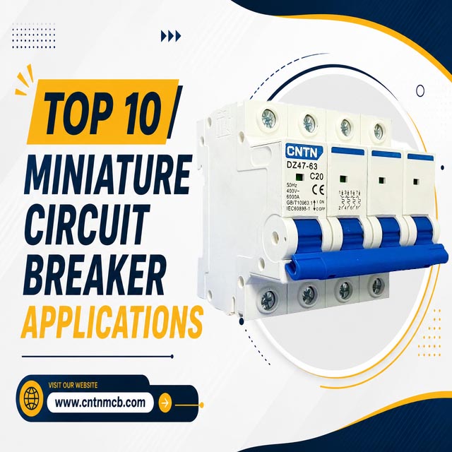
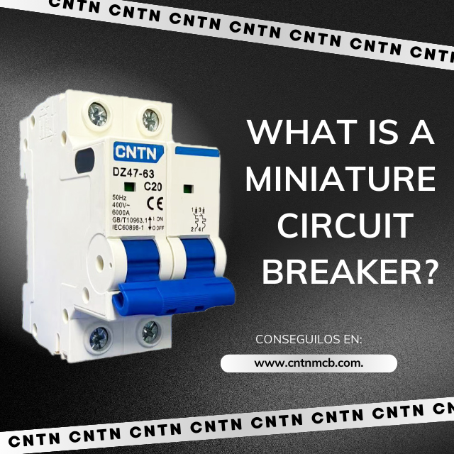
Small circuit breakers (MCBs) are key protective components in low-voltage power distribution systems. They are widely used in residential, commercial, and industrial scenarios, and perform the important functions of overload protection and short-circuit protection. Proper wiring operation is a prerequisite for ensuring the safe and stable operation of electrical circuits.
Next, we will elaborate on the selection, installation methods, wiring process, common issues, and maintenance of miniature circuit breakers, helping electrical practitioners and ordinary users master the correct wiring methods.
Proper selection is the prerequisite for the use of miniature circuit breakers.
The selection of a miniature circuit breaker should match the rated current, number of poles, and tripping characteristics according to the size of the circuit, and its functional type should be matched with reference to the application scenario.
Select the “rated current” according to the circuit current.
Rated current is a core performance indic
ator of miniature circuit breakers, and even an invisible guardian of circuit safety. It enables the circuit breaker to operate stably for a long time without tripping, and accurately matches the circuit load and wire specifications.
Common circuit selection types in households include:
Lighting circuit: The load current is usually ≤10A, which is suitable for a 10A miniature circuit breaker, matched with 1.5mm² copper core wires.
General socket circuits (such as those in living rooms and bedrooms): They need to carry electrical appliances like TVs and refrigerators, with a load current of about 10-16A. A 16A circuit breaker is selected, matched with 2.5mm² copper core wires.
High-power household appliance circuits (such as air conditioners and electric water heaters): A 1.5-horsepower air conditioner has a load of about 5A, and a 2-horsepower air conditioner has a load of about 7A. A 20-25A circuit breaker should be selected, matched with 4mm² copper core wires (to prevent the wires from heating up before the circuit breaker trips due to excessively thin wires).
Note: The rated current of the miniature circuit breaker should be slightly larger than the actual maximum load current of the circuit (usually with a 10%-20% margin reserved), but must not exceed the allowable current-carrying capacity of the wires.
Select the "number of poles" based on the type of circuit.
The number of poles of a miniature circuit breaker refers to the number of circuits it controls, and its selection depends on whether the circuit is single-phase or three-phase, as well as whether the neutral wire needs to be controlled.
1P (single-pole): Controls only the live wire; the neutral wire is connected directly (without passing through the circuit breaker). It is suitable for lighting circuits (after power failure, only the live wire is de-energized while the neutral wire remains energized, so safety precautions are necessary).
2P (double-pole): Controls both the live wire and neutral wire simultaneously. After power failure, the circuit is completely de-energized, offering higher safety. It is suitable for circuits of electrical appliances that come into direct contact with the human body, such as sockets and air conditioners.
3P (three-pole) / 4P (four-pole): The 3P controls the three-phase live wires, while the 4P additionally controls the neutral wire. Both are only suitable for 380V three-phase circuits (e.g., small industrial motors).
Select the “tripping characteristic” according to the load characteristic.
Tripping characteristic refers to how quickly a miniature circuit breaker trips. The common types are B, B, and D. It needs to be matched according to the starting current of the load.
Type B: Trips when the overload current reaches 2-3 times the rated current. At this time, the tripping speed is slow, and it is suitable for pure resistive loads without inrush current.
Type C: Trips when the overload current reaches 5-10 times the rated current. The tripping speed here is medium, and it is the most common type in households.
Type D: Trips when the overload current reaches 10-20 times the rated current. The tripping speed at this time is fast, and it is suitable for loads with large starting currents such as motors and water pumps

Installation specifications are the foundation for the safe use (of miniature circuit breakers).
Standardized and correct installation operations are the prerequisite for ensuring the safe and stable operation of circuits.
Preparation Work Before Installation
Confirmation of power failure: Before installation, the upper-level main power supply must be disconnected, and a test pencil must be used to check that the wires at the installation location are in a power-off state. Live operation is strictly prohibited.
Environmental inspection: The installation location of the miniature circuit breaker must be dry and well-ventilated, and away from water sources, heat sources, and flammable materials.
Tool preparation: Prepare a flathead/crosshead screwdriver (selected according to the type of terminal screw), wire strippers (for processing the wire insulation layer), a test pencil, and insulating gloves.
Core Installation Steps
Wire processing: Use wire strippers to remove the insulation layer from both ends of the wire. The stripping length is 5-8mm (it should match the depth of the circuit breaker terminal, and refer to the product manual if necessary). Stranded copper core wires must be twisted into a single strand to prevent copper wires from scattering.
Wiring operation: Follow the principle of “upper inlet and lower outlet, live wire on the left and neutral wire on the right”.
Connect the incoming wires to the upper terminals (live wire to “L”, neutral wire to “N”), and the outgoing wires to the lower terminals (correspondingly connected to the load).
After inserting the wire into the terminal, use a screwdriver to tighten the screw clockwise. The tightness should be such that “the wire does not loosen when pulled” (too loose may cause poor contact, while too tight may damage the screw or wire).
Final Check after installation final inspection work
Appearance inspection: Confirm that the live wire and neutral wire are not reversed, the exposed part of the wire does not exceed the terminal range, and the miniature circuit breaker is not tilted or loose.
Power-on test: Close the upper-level main power supply, then close the miniature circuit breaker. Use a test pencil to check the outlet terminal (it is normal if the live wire terminal lights up and the neutral wire terminal does not). Meanwhile, observe whether the circuit breaker makes abnormal noises or generates heat.
Troubleshooting: Solutions to Common Problems
During the operation of a miniature circuit breaker, faults such as “failure to close”, “no power after closing”, and “shell heating” may occur.
Fault 1: Failure to close
Troubleshooting steps:
Turn off all loads in the circuit (unplug electrical plugs, turn off light switches) and try to close the breaker. If it can be closed, it indicates that the load is overloaded or there is a local short circuit.
If it still cannot be closed after turning off the load, disconnect the wires at the incoming end of the breaker and test the breaker alone (suspend the wires, close the breaker, and use a multimeter to check if the terminals are conductive):
If the breaker conducts normally after being closed alone, it indicates that there is a short circuit in the line (e.g., damaged wire insulation layer).
If the breaker cannot be closed even when tested alone, it indicates an internal fault of the breaker (e.g., tripper jamming, damaged operating mechanism), and the breaker needs to be replaced with a new one.
Fault 2: No power to the load after closing
Troubleshooting steps:
Use a test pencil to check the incoming end of the breaker (if there is no power at the incoming end, it indicates a fault in the upper-level power supply, such as a trip of the main switch).
If there is power at the incoming end, check the outgoing end (if there is no power at the outgoing end, it may be due to loose wiring; the terminal screws need to be re-tightened after power failure, or the wires are not properly connected).
If there is power at the outgoing end but no power to the load, check the downstream lines (e.g., whether the wiring of sockets or lamps is loose).
Fault 3: Heating of the breaker shell during operation
Normal heating: Slight warmth on the shell during operation (≤40℃) is normal, as there is contact resistance when current passes through the terminals, which generates a small amount of heat.
Abnormal heating: If the shell temperature exceeds 50℃ (feels hot to the touch) or is accompanied by an unusual odor (e.g., burning plastic smell), immediately open the breaker for troubleshooting:
Check if the terminal screws are loose (the most common cause; re-tighten after power failure).
Check if the wire specifications are matched (e.g., a 2.5mm² wire connected to a 32A breaker, where insufficient current-carrying capacity of the wire causes heat to conduct to the breaker).
Check if the breaker is overloaded (use a clamp ammeter to measure the circuit current; if it exceeds the rated value, reduce the load).
Maintenance: Extend Service Life and Ensure Performance
The maintenance of miniature circuit breakers is simple yet important. Regular inspections can help detect potential issues in a timely manner and extend their service life (the normal service life is approximately 8-10 years).
Regular Inspection (Once Every 3-6 Months)
Appearance inspection: Check if the circuit breaker shell has cracks or discoloration (such as yellowing or blackening, which may be caused by overheating), and if the terminals have signs of ablation (such as blackened copper terminals).
Wiring inspection: After power failure, gently twist the terminal screws with a screwdriver to confirm they are not loose (screws may loosen due to vibration during long-term operation).
Operation inspection: Manually open and close the breaker 2-3 times to check if the handle operates smoothly (no jamming or excessive play), and confirm that the protection mechanism is functioning normally.
Additional Maintenance for Special Scenarios
Humid environments (e.g., bathrooms, kitchens): Inspect once every 2 months. Check if there is condensation on the circuit breaker (humidity may cause terminal rusting).
Desiccants (e.g., silica gel packs) can be placed inside the distribution box.
After thunderstorm seasons: Thunderstorms may cause voltage fluctuations due to lightning strikes. Check if the circuit breaker has tripped and if its shell is damaged. If it cannot be closed after tripping, check whether internal components are damaged by surge currents.
Replace Aged Circuit Breakers in a Timely Manner
Even if the service life has not been reached, the circuit breaker must be replaced in a timely manner if the following conditions occur:
- Obvious cracks, deformation or ablation marks on the shell;
- Sticking during opening/closing operations, or loose handle after closing (unable to stay in the “ON” position);
- Frequent tripping (after ruling out load and line issues), or excessively long cooling time after tripping (unable to close even after more than 5 minutes);
- Having been in use for more than 10 years (the plastic shell may age, leading to reduced insulation performance).
The warmth of a home starts with safety; the safety of electrical circuits begins with a small circuit breaker!
Though small in size and seemingly simple in structure, the miniature circuit breaker hides “solid capabilities” to safeguard the entire family’s electrical safety.
When the circuit encounters dangers such as overload or short circuit, it can cut off the power supply in milliseconds, preventing wire burnout and electrical appliance damage, and more importantly, eliminating fire hazards at the source.
Conclusion
The miniature circuit breaker is the first and most critical line of defense for a home’s electrical system!
Correct selection, standardized installation, and proper operation will make this safety line impenetrable, allowing you to use electricity with true peace of mind.
CNTN® is committed to manufacturing miniature circuit breakers. Please feel free to contact us if you have any requirements.